

How to Connect M12 Ethernet Connectors for IP67 Industrial Cameras
Time:Aug 26,2026
Source:
IP67 industrial cameras are built for places where ordinary network connections are vulnerable: automated inspection cells, robotic workstations, packaging equipment, production lines, and outdoor machinery. In these environments, a camera cable must do more than transfer data. It must remain stable under vibration, resist contaminants, fit into limited installation space, and preserve the environmental protection expected from the camera enclosure.
That is why M12 Ethernet connectors are widely specified for machine vision equipment. Their threaded coupling gives the camera-side connection a secure mechanical lock, while coded interfaces help prevent the wrong cable from being installed. However, an M12 connection is only reliable when the coding, cable construction, shielding, mating method, and system power arrangement all match the actual camera application.
At Torven, we manufacture cable and connector assemblies for industrial automation and machine vision systems. Our work covers the practical connection requirements behind camera deployment: Ethernet data transmission, camera power, trigger and I/O signals, flexible routing, ruggedized connector termination, and customized cable assemblies for equipment builders. This article explains how to make a dependable M12 Ethernet connection while showing what should be considered before a cable is specified for an IP67 industrial camera.
Why IP67 Industrial Cameras Use M12 Ethernet Connections
A standard RJ45 plug works well in a protected office or control cabinet, but it is not normally the preferred camera-side interface for wet, dusty, mobile, or vibration-heavy machinery. Industrial cameras need a connection that can remain mechanically secure while maintaining reliable Ethernet communication near motors, drives, actuators, and moving equipment.
M12 Ethernet connectors address these needs through a compact circular interface, threaded locking, defined mechanical keying, and compatibility with shielded industrial Ethernet cable designs. Once correctly mated with the appropriate sealing elements, the M12 interface helps the camera maintain its intended environmental protection at the data connection.
The benefit is not limited to ingress protection. Secure coupling also reduces the risk of accidental disconnection during machine maintenance, cable movement, or vibration. This is particularly important for vision systems where a brief link interruption can stop inspection, create rejected production output, or interrupt traceability data.

Start With the Camera Interface, Not the Cable
The first step is to identify the Ethernet interface specified by the camera manufacturer. Do not choose a cable based only on the fact that the camera has an M12 connector. M12 is a connector family, and cameras may use similar circular interfaces for Ethernet, power, trigger signals, lighting, or general I/O.
Read the camera label, connector drawing, and technical documentation before selecting a cable. Confirm the Ethernet coding, pin count, connector gender, required network speed, power method, and cable requirements. These details determine whether the installation needs a D-coded 4-pin cable, an X-coded 8-pin cable, a camera-to-RJ45 assembly, or a different dedicated interface.
This identification step also protects the rest of the vision system. A camera may have one connector for Ethernet and another for DC power, even when both use circular industrial connector shells. Connecting the wrong assembly to the wrong port can prevent operation and may create unnecessary troubleshooting work.
Choose D-Coded or X-Coded M12 Ethernet Correctly
M12 D-Coded Connections for Fast Ethernet
M12 D-coded Ethernet connectors commonly use four contacts and two differential pairs. They are generally used for Fast Ethernet applications where the camera or network architecture operates at 10/100 Mbps. When a camera specifies D-coded Ethernet, use a matching D-coded cable assembly and verify that the complete network path is designed for the required speed.
A D-coded cable should not be used as a substitute for an X-coded cable in a Gigabit camera system. The coding, contact structure, and transmission capability are different. Selecting the correct coding at the beginning avoids later issues with link speed, camera detection, or unstable image transfer.
M12 X-Coded Connections for GigE Vision
M12 X-coded connectors commonly use eight contacts and four differential pairs. This arrangement is widely used where machine vision equipment requires Gigabit Ethernet or higher-bandwidth industrial communication. It is relevant to GigE Vision cameras, high-resolution inspection, high-frame-rate capture, and production systems that need dependable image transmission.
Because X-coded connections support a four-pair Ethernet structure, the cable assembly must preserve pair integrity and shield continuity. The cable category, conductor construction, connector termination, and overall routing all affect real-world network performance. A high-speed camera link is only as reliable as the weakest part of the completed connection.
Build the Right Connection From Camera to Controller
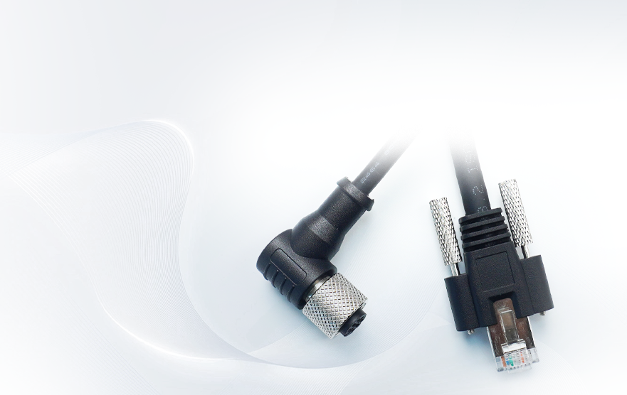
Many installations use an M12 connector at the camera and an RJ45 connector at the controller, switch, or industrial PC. The M12 end manages the demanding field-side conditions, while the RJ45 end is normally kept inside a cabinet or protected machine enclosure. This arrangement provides a practical route between an IP67 camera and standard Ethernet equipment.
For systems requiring a camera-side M12 interface and a protected network-side RJ45 interface, Torven’s industrial camera Ethernet cable category is designed around machine vision connectivity needs. It belongs to a wider industrial vision cable range used to transmit image data and control signals between cameras, controllers, and sensors.
Choosing the cable construction requires more than confirming the two connector ends. Define the required length, target data rate, camera model, connector gender, straight or right-angle orientation, cable routing path, and motion condition. A cable routed through a cable carrier needs a different design focus from one installed along a fixed machine frame.
In high-noise areas, shielded cable construction is particularly important. Servo systems, VFDs, motors, and switching equipment can influence Ethernet performance when shielding is incomplete or cable routing is poorly planned. A correctly designed shield path helps protect transmission stability and supports consistent image acquisition.
How to Connect the M12 Ethernet Connector
Inspect Before Mating
Inspect the camera receptacle and cable connector before installation. Check the connector keyway, contacts, coupling thread, O-ring, sealing surfaces, cable jacket, and strain-relief area. The mating faces should be clean and dry, and the connector should not show corrosion, bent contacts, cracks, or jacket damage.
The condition of the O-ring matters. If it is missing, cut, flattened, contaminated, or incorrectly positioned, the connection may no longer support the required sealing performance. Replace damaged sealing elements before putting the equipment into service.
Align and Lock the Cable
Align the connector keyway with the camera port and insert the connector straight. Do not use force to overcome resistance. If the connector does not mate smoothly, stop and verify the coding, orientation, contact condition, and connector compatibility.
Once fully seated, tighten the threaded coupling nut according to the torque requirement specified for the camera and connector. A loose connection can allow vibration-related movement, signal interruption, and sealing failure. Excessive tightening can damage the coupling components or the sealing interface.
Connect and Protect the Host-Side Interface
Connect the other end of the cable to the switch, industrial PC, vision controller, or approved PoE device. If this end uses RJ45, protect it in an enclosure suited to the actual operating environment. The M12 camera-side connection may be IP67, but a standard exposed RJ45 connection should not be assumed to provide the same level of protection.
Close all unused camera interfaces with compatible protective caps. An unused port left open can compromise the camera enclosure, regardless of how well the Ethernet connector has been installed.
Maintain Signal Quality With Proper Shielding
Machine vision systems depend on stable data transmission. A camera may appear to work during initial commissioning but suffer intermittent frame loss or network dropouts once motors, conveyor drives, or robot cells begin operating. These failures often point to cable shielding, termination quality, routing, or motion stress rather than the camera itself.
Use shielded cable assemblies that are appropriate for the operating environment, and maintain shield continuity through the connector structure. Keep conductor untwisting to a minimum during field termination and avoid leaving long, loose shield tails at the connector. Cable routes should also avoid unnecessary parallel runs alongside high-power motor cables where possible.
Torven develops industrial vision cable assemblies for camera, controller, and sensor connections. Available solution directions include data transmission, camera power, trigger and control connections, with cable configurations intended for industrial conditions such as oil exposure, low temperatures, EMI, and continuous movement. This product focus allows the cable design to be selected around the vision system’s installation conditions rather than treated as a generic network accessory.

Check PoE and Separate Power Requirements
Some industrial cameras accept Power over Ethernet, while others use Ethernet only for data and require a separate DC power connection. The presence of an M12 Ethernet connector does not confirm PoE compatibility by itself.
Before connecting PoE equipment, verify the camera power specification, switch or injector output, available power budget, and approved cable configuration. If the camera needs separate DC power, use the designated power interface. Do not attempt to supply power through a data interface unless the camera documentation explicitly supports that arrangement.
Machine vision systems often require more than an Ethernet cable. A complete installation may include data, power, trigger, lighting, and I/O connections. This is why cable selection should be reviewed as a system-level decision, particularly when the camera is mounted in a moving or exposed location.
How Torven Supports Industrial Camera Cable Requirements
Reliable camera connectivity depends on the details that are often decided before installation begins: connector coding, connector orientation, conductor count, shield construction, jacket material, bend performance, environmental protection, and the opposite-end interface. Torven manufactures cable and connector assemblies around these practical variables for industrial automation and machine vision applications.
Our product offering includes M-series connection options spanning M5, M8, M12, M16, and M23 formats, with threaded connector structures available in straight, angled, and flange styles. Depending on the application, cable assemblies can be configured with different core counts and interfaces for data, signal, power, and camera-related connectivity.
For automation applications, Torven supports M12 coding options including A, B, D, X, S, K, T, L, and US coding. The available cable construction options include PVC, PUR, and TPE jackets for applications that require particular flexibility, abrasion resistance, or environmental suitability. Our automation connection solutions also support requirements related to Ethernet, EtherCAT, PROFINET, PoE, IEEE 802.3, and harsh-environment protection.
Where a camera connection must operate near robotics, drag chains, or frequently moving machine elements, the cable needs more than a standard fixed-installation design. Torven’s automation cable solutions address applications involving sensors, robotics, drives, Industry 4.0 equipment, and IIoT connectivity, with options described for high-flex, abrasion-resistant, chemical-resistant, and IP-rated requirements.
This application-driven approach helps equipment builders specify a connection that matches the camera interface and the actual service environment. Instead of treating the cable as a standard accessory, the assembly can be selected around the network speed, mechanical movement, installation space, protection requirements, and connection architecture of the finished machine.

Troubleshoot M12 Ethernet Camera Problems
No Ethernet Link
Confirm that the connector coding, pin count, gender, and keyway match the camera Ethernet port. Inspect the mating condition, thread engagement, contacts, and cable path. Also confirm that the cable is connected to the Ethernet port rather than a power, trigger, or I/O port.
Camera Is Not Detected
Check the camera power source, PoE availability where applicable, network link indicators, IP address configuration, subnet settings, and switch port configuration. A correctly installed cable cannot resolve a host-side network configuration mismatch.
Intermittent Image Loss
Inspect shield continuity, cable routing, bend radius, connector tightness, and strain relief. Consider whether the cable experiences repetitive movement, vibration, torsion, or high electromagnetic interference. A cable designed for static routing may not remain reliable on a moving machine assembly.
Water Ingress or Corrosion
Check the O-ring, connector seal, thread engagement, cable jacket, cable gland, and unused-port caps. Replace damaged parts before continuing operation. Environmental protection must be maintained across every exposed connection point.
Specify the Correct Cable Assembly
When requesting an M12 Ethernet cable for an IP67 industrial camera, provide the camera brand and exact model, connector photo or drawing, coding, pin count, connector gender, required length, required network speed, power method, and opposite-end interface.
Include the installation environment as well. Oil, washdown exposure, chemicals, low temperatures, UV, vibration, robotic movement, drag-chain routing, and high EMI all influence cable-jacket selection, shielding, connector structure, and expected service life.
A dependable M12 Ethernet connection begins with the correct camera interface identification and ends with a cable assembly designed for the actual machine environment. With properly matched coding, shielding, sealing, and cable construction, IP67 industrial cameras can maintain stable communication throughout demanding production conditions.

Apply Here For A Custom Made Solution

Shenzhen Torvenics Electronic Co.,Ltd.
615 Block A, No.11 Tangkeng Road,Henggang Longgang Dist,Shenzhen China