

How to Wire Circular Connector Cables: A Step-by-Step Guide
Time:Oct 15,2026
Source:
Circular connector cables are widely used in industrial automation, sensors, machine vision, robotics, and control systems. However, choosing the right connector is only part of the installation process. Incorrect pin assignment, loose connections, excessive bending, or poor cable routing can cause signal loss, intermittent faults, or even equipment damage.
Whether you are learning how to wire circular connectors cables or installing an Industrial Vision cable, following a structured wiring and installation process can significantly improve connection reliability.

Check the Connector and Cable Specifications First
Before wiring, confirm the basic specifications of the connector cable and the equipment it will connect to.
Check:
- Connector type and size, such as M5, M8, M12, or M16
- Number of pins or contacts
- Male or female connector
- Cable core count
- Rated voltage and current
- Signal or data transmission requirements
- Shielding configuration
- Connector pinout
- IP protection requirements
Circular connector cables can have different pin configurations even when they have the same connector size. For this reason, never assume that two cables with the same connector diameter have the same wiring arrangement.
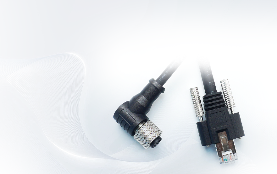
For industrial automation applications, pre-assembled M-series cables can simplify installation and reduce the risk of incorrect termination. Torven offers M5, M8 and M12 connector cable solutions with different connector configurations, cable lengths and termination options.
Need a ready-to-install circular connector cable? Explore Torven’s M5, M8 and M12 connector cable solutions to find a configuration that matches your application.
Identify the Pinout Before Wiring
The most important step when wiring a circular connector is confirming the correct pin assignment.
A typical connector may include separate contacts for:
- Power supply
- Ground or common
- Signal transmission
- Trigger input
- Trigger output
- Communication or data lines
- Shielding
The exact pinout depends on the connector and equipment manufacturer. Always compare the connector datasheet with the device wiring diagram before connecting the cable.
For example, an Industrial Vision cable may carry both power and control signals between a camera and other machine components. Reversing power and signal contacts can prevent the system from operating correctly and may damage sensitive electronics.
Do not rely only on wire colors
Wire colors can vary between cable constructions and manufacturers. The safest approach is to identify each conductor by the manufacturer's wiring diagram, connector pin number, and equipment documentation.
Prepare the Cable and Connector
If you are assembling a field-terminated circular connector cable, prepare the cable carefully before making the electrical connection.
A basic process is:
- Measure the required cable length.
- Cut the cable cleanly.
- Strip the outer jacket to the specified length.
- Separate the individual conductors.
- Strip the conductor insulation according to the connector specification.
- Identify each conductor against the pinout.
- Terminate each conductor using the specified contact method.
- Check that no conductor is loose or accidentally touching another contact.
Avoid removing more insulation than necessary. Excessively exposed conductors can increase the risk of short circuits and reduce mechanical protection.
For production environments, using factory-terminated cable assemblies can be preferable because the connector termination, cable construction, and electrical configuration can be controlled as one assembly.
Connect the Wires to the Correct Pins
Once the conductors are prepared, connect each wire to its designated contact.
For solder-cup connectors, make sure the conductor is properly positioned before soldering. For crimp-style contacts, use the correct crimping tool and verify that the crimp is mechanically secure.
After termination, check:
- Correct pin-to-wire assignment
- No loose strands
- No short circuit between adjacent contacts
- Proper conductor insertion
- Secure strain relief
- Correct shield connection where required
For high-speed Industrial Vision cable applications, maintaining the cable's original electrical structure is particularly important. Excessive untwisting, poor shielding termination, or inconsistent termination can affect signal integrity.
Install and Lock the Circular Connector
After wiring, carefully mate the connector with the corresponding socket.
Align the connector key or orientation feature first. Do not force the connector into place.
For threaded circular connectors, tighten the coupling nut according to the connector manufacturer's specification. The connector should be secure enough to resist vibration, but excessive force should be avoided.
A properly installed connector should:
- Seat completely
- Have the correct orientation
- Be mechanically locked
- Have no visible gap caused by incorrect mating
- Maintain the required sealing performance
This is particularly important in industrial environments where vibration, dust, water, oil, or repeated machine movement may affect the connection.
Route the Cable Correctly
Correct wiring does not guarantee reliable operation if the cable is poorly installed.
During installation, avoid:
- Sharp bends immediately behind the connector
- Excessive pulling force
- Crushing the cable under machine components
- Continuous twisting
- Routing high-speed signal cables directly beside strong EMI sources
- Exceeding the cable's minimum bend radius
For moving equipment, such as robots and drag chains, select a cable specifically designed for continuous flexing rather than treating a standard static cable as a motion cable.
Industrial Vision cables may also require additional attention to shielding, bending, cable length, and electromagnetic interference because image data must remain stable during continuous operation. Torven's Industrial Vision cable range includes camera power/trigger and industrial Ethernet cable solutions.
Installing a machine vision system? Check Torven’s Industrial Vision cable solutions for camera power, trigger, Ethernet, and other vision-system connection requirements.
Test the Connection Before Full Operation
Before powering the complete system, perform a basic connection check.
For electrical connections, verify continuity and check for unintended shorts where appropriate. Then confirm that the connector is correctly seated and that the cable has no visible damage.
For an Industrial Vision cable installation, check whether:
- The camera is detected correctly
- Data transmission is stable
- Trigger signals operate correctly
- The image stream remains consistent
- No intermittent connection occurs when the cable is gently moved
If the system shows intermittent image loss or communication errors, inspect the connector seating, pin assignment, shielding, cable routing, and cable length before replacing other components.
Common Wiring Mistakes to Avoid
Several installation mistakes occur repeatedly when wiring circular connector cables:
Using the wrong pinout: The connector may physically fit while the electrical configuration is incorrect.
Forcing mismatched connectors: Never use mechanical force to compensate for incorrect connector orientation or type.
Ignoring shielding: High-speed data and vision applications can be sensitive to electromagnetic interference.
Over-bending the cable: Tight bends near the connector can place mechanical stress on the termination.
Leaving the connector loose: Vibration can gradually weaken an improperly secured connection.
Skipping testing: A connection that looks correct visually may still contain a wiring or continuity problem.
Conclusion
Learning how to wire circular connectors cables is mainly about controlling the entire installation process, not simply connecting individual wires. Confirm the connector and pinout first, terminate each conductor correctly, secure the connector, route the cable properly, and test the finished connection before putting the equipment into continuous operation.
For Industrial Vision cable installations, additional attention should be given to signal integrity, shielding, cable routing, bandwidth, and mechanical movement. Using a properly specified and professionally assembled cable can reduce wiring errors and simplify installation.
Looking for reliable circular connector or Industrial Vision cable assemblies? Contact Torven for standard or customized cable solutions based on your connector type, pinout, length, shielding, and application requirements.

Apply Here For A Custom Made Solution

Shenzhen Torvenics Electronic Co.,Ltd.
615 Block A, No.11 Tangkeng Road,Henggang Longgang Dist,Shenzhen China